Before you begin
Be careful to protect the components from electrostatic discharge. This is most critical for the ICs and the diodes.
If you have not soldered before you should read a soldering tutorial. There are links to several good tutorials on the Adafruit website.
I also highly recommend the Soldering is Easy comic book by MightOhm.
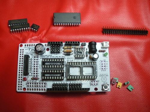
Step 1 – Verify kit contents
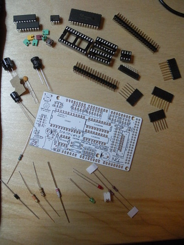
Note that kits sold after Jan 1, 2013 no longer include the small white JST power connector.
Also note that there are 6 jumpers and your kit may include multiple colors or all the same color.
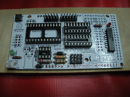
Step 2 – IC sockets, power, ink, & reset switch
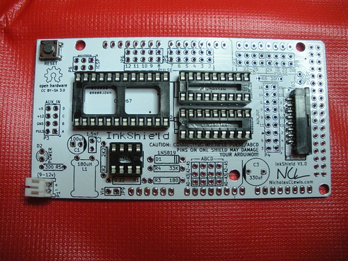
Note that kits sold after Jan 1, 2013 no longer include the small white JST power connector (lower left corner).
Pay attention to the orientation of the IC sockets (the notches should line up with the notch symbol on the PCB)
Step 3 – Boost resistors and diode
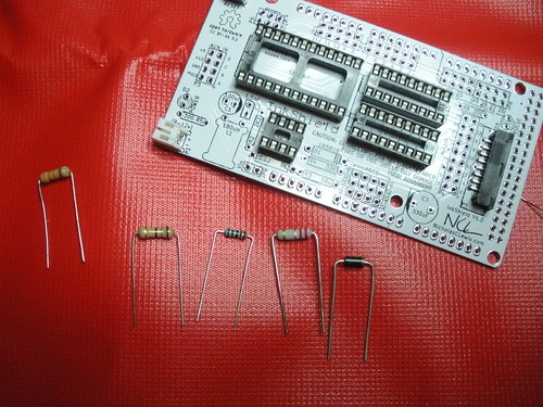
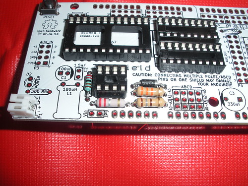
Pay attention to the orientation of the diode (the white band should line up with the bands on the PCB)
Step 4 – LEDs & LED resistors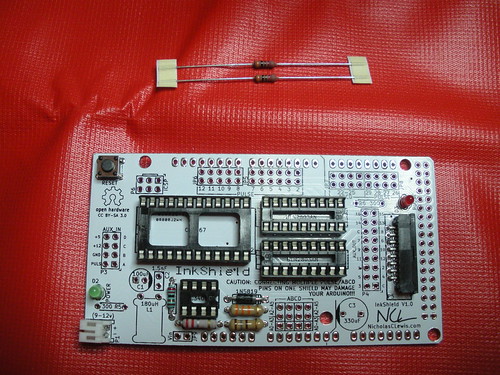
Pay attention to the orientation of the LEDs (the flat side should line up with the flat side on the PCB)
Step 5 – Male headers
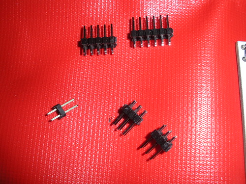
Breakaway the following from the 18×2 strip:
1 – 1×2
2 – 3×2
1 – 5×2
1 – 6×2
The 3x2s go on the A0-A5 jumpers and make a 3×4 total array.
Step 6 – Capacitors and inductor
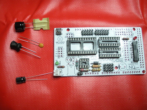
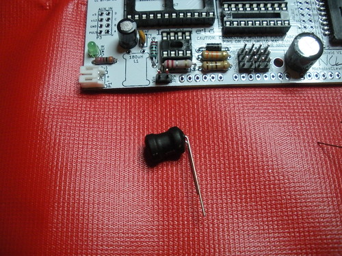
Bend the inductor leads over so that it will lay on its side on the PCB.
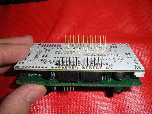
Step 7 – Stackable headers
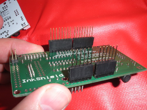
It is easiest to place the stackable headers on another shield and then place the shield on to them to solder.
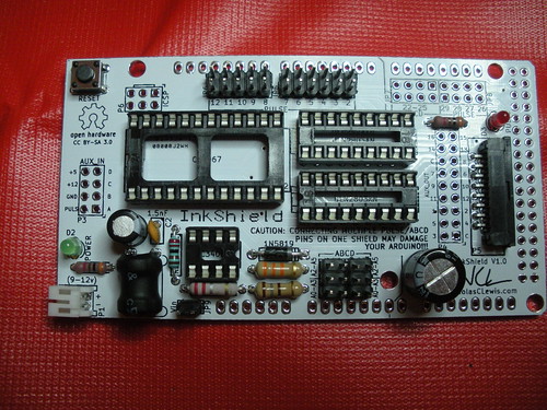
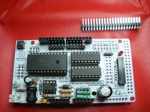
Step 8 – ICs and jumpers
Install the ICs (again note the orientation of the ICs in the sockets the notches should line up) and the jumpers (A0-A3, 2, and Vin are good places to start, see the use page for more information). You can split the extra male headers up and install them on the aux_in, aux_out, ISP, or add them for Arduino Mega support.
Basic Testing
Visually ensure that you do not have any solder bridging adjacent pins. You can also check them with a multimeter to ensure that only the pins that should be connected according to the schematic are connected.
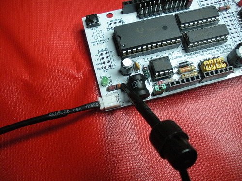
You can then power up the board using either the Vin in the lower left corner or by supplying power to the Vin and ground pins of the stackable headers. Then check the following voltages:
Ground point
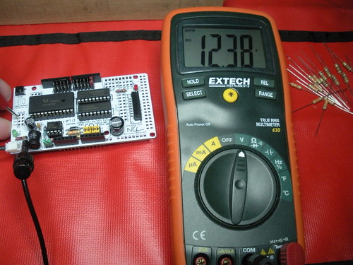
Check "12v" line
Check "5v" line
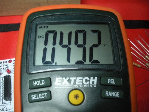
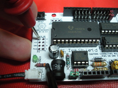
With the shield disconnected from the Arduino you should not have more than about 0.5v on the "5v" line or on any of the ABCD or Pulse lines
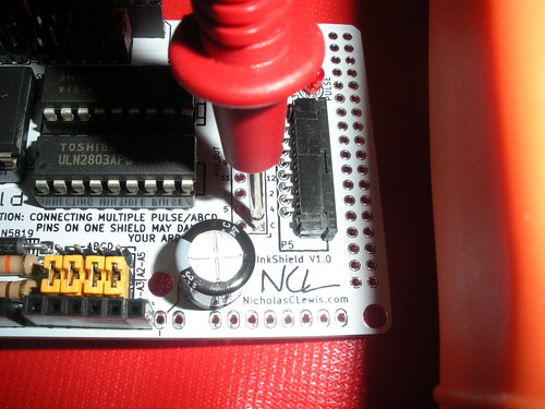
Check "20v" line using either of the "C" pins on the aux header
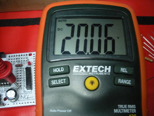
Check "20v" line using either of the "C" pins on the aux header
If all of these voltages check out than you can proceed to the use page